| |
|
|
|||||
| |
|||||||
| |
|
|
|
|
|
||
| |
|
|
|
|
|
|
|
PARD is the periodic and random deviation of the DC output voltage from its average value over a specified bandwidth with all other parameter constant. It is representative of all undesirable AC and noise components remaining in the DC output voltage after regulation and filtering.
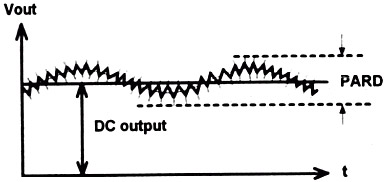
PARD consists
of Undesirable signals superimposed on the DC output of a power supply. PARD
is measured normally in Peak to Peak values, and is typically specified over
a bandwidth range from 20Hz to 20MHz. Any deviation below 20Hz is included in
a specification called output drift. To make PARD measurements, an Electronic
Load should have lower PARD than the power supply being tested. A regulated
AC source should be applied to the input of the power supply under test. PARD
measurements are made at the lowest and highest specified value of AC input
to the power supply. Proper connection between the instruments and power supply
under test are essential when making these measurements since PARD consists
of low level, wide band signals. Major test concerns are ground loops, proper
shielding, and impedance matching. An oscilloscope can be used for peak to peak
measurements, to eliminate cable ringing and standing waves. The typical configuration
includes coaxial cabling with 50W
termination at both ends. Capacitors should be connected in series with the
signal path to block the DC current. It should use instruments with floating
(differential amplifier) input to eliminate Ground Loop problem between power
supply and testing equipments.
Prodigit 3310/3320 series and 3600A DC Electronic Load has a low PARD which is suitable to test the PARD of a power supply, the 4030 and 3600A PARD measurement has a differential 50W impedance input circuit configuration, it can measure up to four output PARD simultaneously.
1.6 Input Power and Efficiency
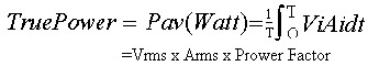
The efficiency of a power supply is the ratio of its total output power to its total input power. For a typical AC to DC power supply, the input power must be true power or average power, not just Vrms x Arms.
The formula for efficiency is
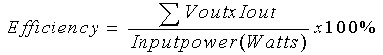
Power supply efficiency provides verification of correct operation. If efficiency is outside the specified range there is either a design flaw or a problem with the individual unit.
Efficiency should be measured under steady - state operation after the unit been allowed to warm up.
For some power supplies, efficiency is a function of loading. In this case, the load should be varied to provide ample data to plot effective test results.
The 3600A testers, measures efficiency utilizing their AC source electronic loads. True power measurement circuitry requires adequate time to read the DC load. Allow for more setting time to get stable readings when changing input. As for PARD measurements, normally needs more time than DC load V/A, as a result, needs more setting time to get stable reading when large input power is changed. Please use the same rule as described in PARD measurement: set Tmeas.n to higher value (for example: 2 sec.) to get a stable PARD reading rather than to lower Tmeas.n value which would result in an unstable PARD reading. Finally, add a reasonable Tmeas.n margin (for example 20% or more) to get stable readings at every measurement. Taking these steps will provide stable and accurate reading with a minimum of testing time.
1.7 Dynamic load or Transient load
A constant voltage output DC power supply is designed with a feedback loop which continuously maintains the output voltage at a steady-state level. The feedback loop has a finite bandwidth which limits the ability of the power supply to response to a change in the load current. If the phase shift between the loop input and output is 180 degree at its unity gain crossover, the power supply will become unstable and oscillate.
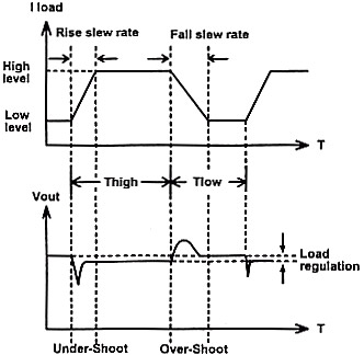
Typically, loads are dynamic rather than exhibiting a steady state current. (For example: a Hard/Floppy disk drive, CPU, RAM etc. draws higher current on start up.) Therefore, dynamic response testing is very important when testing a power supply. The dynamic load can emulate the worst case real world load for testing a power supply, such as High/Low load period, Rise/Fall slew rate, and High/Low load level. If a power supply can pass dynamic load testing in accordance with its output specifications and not to generate overshoot/undershoot on its output voltage then it is considered good.
Steps for setting the Dynamic Loading:
1. Using an oscilloscope to measure the actual load current wave form in your system (computer, printer, etc.) and record each real dynamic load current. 2. Using setting to simulate the worst case dynamic load current wave forms to the test power supply. For a step load current change, a marginally stable power supply will have a ringing voltage output; this could be damage voltage sensitive loads, such as logic circuitry in a computer. Step load current response testing checks critical test points, such as defective output filter, capacitor or loose capacitor connection etc.
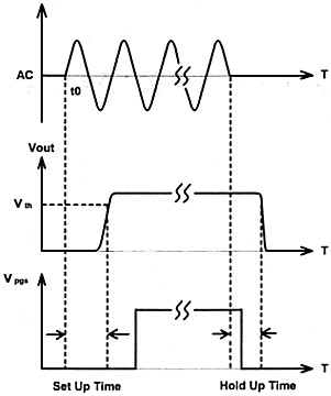
1.8 Power Good/Power Fail (Power Good Signal)
The Power Good Signal (PGS) is a signal sent to a computer system to indicate that the specified power was provided after output became stable. The Power Fail Signal indicates the power supply's output is dropped below or each before the specified output. This is normally indicated as a logic level change; logic 1, or high, equals power good; logic 0 or low, equals power fail.
Please see below figure:
![]()
![]()
![]()
![]()